OENG1168 Engineering Capstone · RMIT University · 2026

KnuckeyRover

A prototype autonomy layer for controlled traffic farming.

Six RMIT engineering students built a 50 kg rover with Knuckey Agricultural Engineering of Winchelsea. It follows the tramlines a grower has already mapped, and it stops itself when something goes wrong. This site sets out how far we got this year and where the rover still falls short.

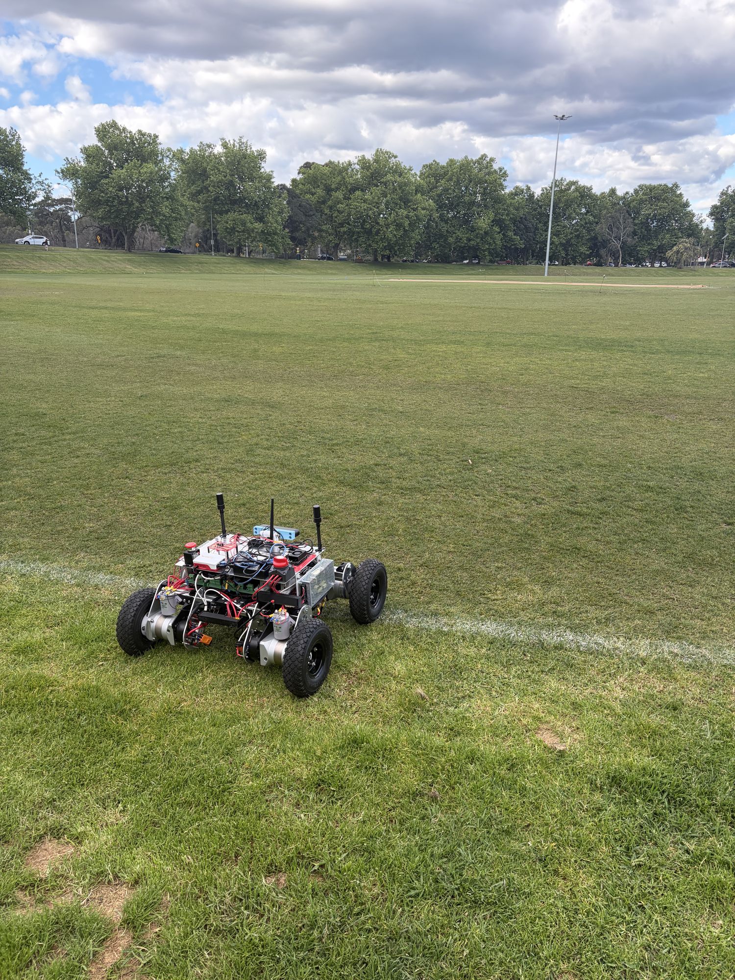
Prototype 2, a four-wheeled aluminium rover with three antenna masts, sitting on a mown grass oval beside a painted line, with trees and cloudy sky behind.
Prototype 2 on grass, 16 October 2026
  • 760 × 740 mm, about 50 kg
  • 4 × ODrive M8325s, 10:1
  • 12S LiPo, 50.4 V max
  • UM982 dual-antenna RTK
  • ROS 2 Jazzy on a Pi 5
  • ZED 2i on a Jetson Orin

01 The problem

Seeding can't wait for a driver

Broadacre farms struggle to hire skilled operators, and ABARES surveys found the difficulty grows the further a farm sits from a big town. Seeding still has to happen inside a few weeks. South Australian trials that sowed wheat three weeks late lost about a tonne per hectare.

1t/halost to a three-week sowing delay in wheat, Washpool SA, 2019 Ref
±20–50mmhow closely neighbouring passes must line up, set by the seeder's tine spacing Site visit
02 Controlled traffic farming

The lines are already on the ground

Controlled traffic farming keeps every machine on the same permanent wheel tracks, called tramlines, so nothing ever drives on the soil between them. Growers map the tramlines with RTK GPS and reuse them every season. For a robot, that is about as much structure as a paddock can offer.

About 30% of Australian cropland runs CTF, and more than 60% in central Queensland. South Australia, the Victorian Mallee and the other low-rainfall zones in the south-east sit near 5%. Ref

The paddock drawn here is P-Middle West near Winchelsea, built from the grower's own John Deere guidance line.

03 The approach

Follow the map the grower already has

Knuckey's customers already map their paddocks, so the rover doesn't build a map of its own. A script turns the grower's AB line into 162 waypoints: 81 working passes of 690.1 m, each with its own heading, and a 12 m step across the headland between them.

The whole plan lives on the rover. If the radio drops a packet, the rover still knows where it is going next.

04 Simulation

One paddock, 8 hours 28 minutes, no aborts

We drove the full route in NVIDIA Isaac Sim with the real ROS 2 navigation stack: 56.9 km at 2 m/s in a single attempt, with no recovery behaviours and no restarts.

99.95%of the 67 ha target area covered by a 12 m implement swept along the logged path Sim
5.7mmRMS error in the 12 m spacing between neighbouring passes Sim

The simulated rover is a 20 kg, 0.4 × 0.3 m body with noise-free GNSS by default. Read these figures as a best case for the navigation software. They don't predict how Prototype 2 will track.

05 Localisation

Bare soil gives a camera nothing to hold onto

We started out planning visual and LiDAR SLAM. Prototype 1 and the research both pointed the same way: a prepared paddock looks the same for hundreds of metres, so feature matching drifts, and dust and glare make it worse. Part-way through semester 1 we dropped SLAM and built around an absolute position reference instead.

Prototype 2 fuses three sensors that fail in different ways. Two extended Kalman filters combine them: a local filter that stays smooth for the controller, and a global filter that stays anchored to the paddock.

SensorWhat it givesWhere it fails
Unicore UM982 dual-antenna RTKCentimetre position, and a heading from the antenna baseline even when the rover is stationaryNeeds a live correction stream and open sky
ZED 2i inertial unitAngular rate and acceleration between GNSS fixesDrifts over time
Encoders on four ODrive S1 drivesWheel speed, giving forward speed and yaw rateA skid-steer rover slips sideways in every turn
Prototype 2 · 760 mm 740 mm P1 270 × 180 mm Wheel ⌀ 260 mm Wheel ⌀ 69 mm Top view and wheels at one scale, 0.4 px per mm
To scale. Prototype 1 fits inside one corner of Prototype 2. No photograph of Prototype 1 is in the project records yet.

06 The machine

Two prototypes

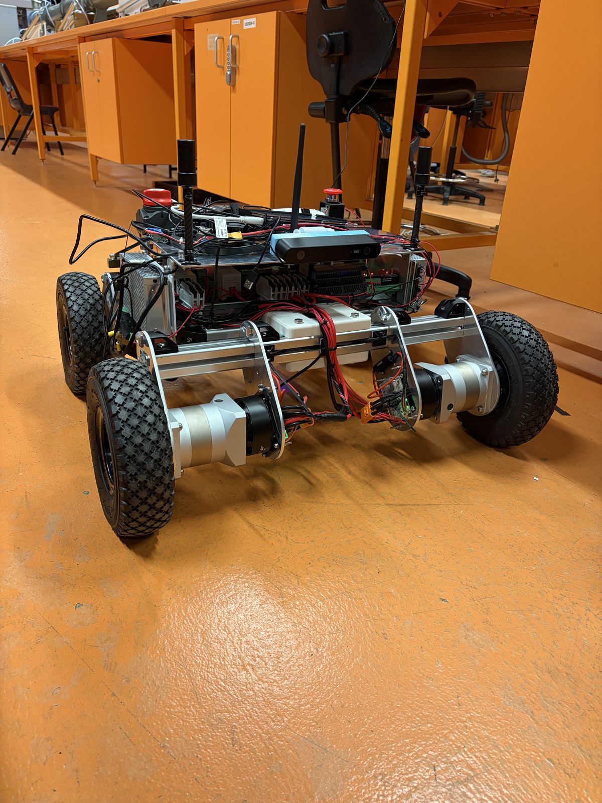
Prototype 1 was a 3D-printed box, 270 × 180 mm, on four N20 gearmotors. It proved the software chain from a PlayStation controller, through ROS 2 on a Raspberry Pi 5, down to the wheels.

It taught us two things the hard way. A control loop can be perfectly stable while it drives the wrong way. And a Pi that shares a power rail with the motors corrupts its own SD card.

21 August 2026

A frame sized for a paddock

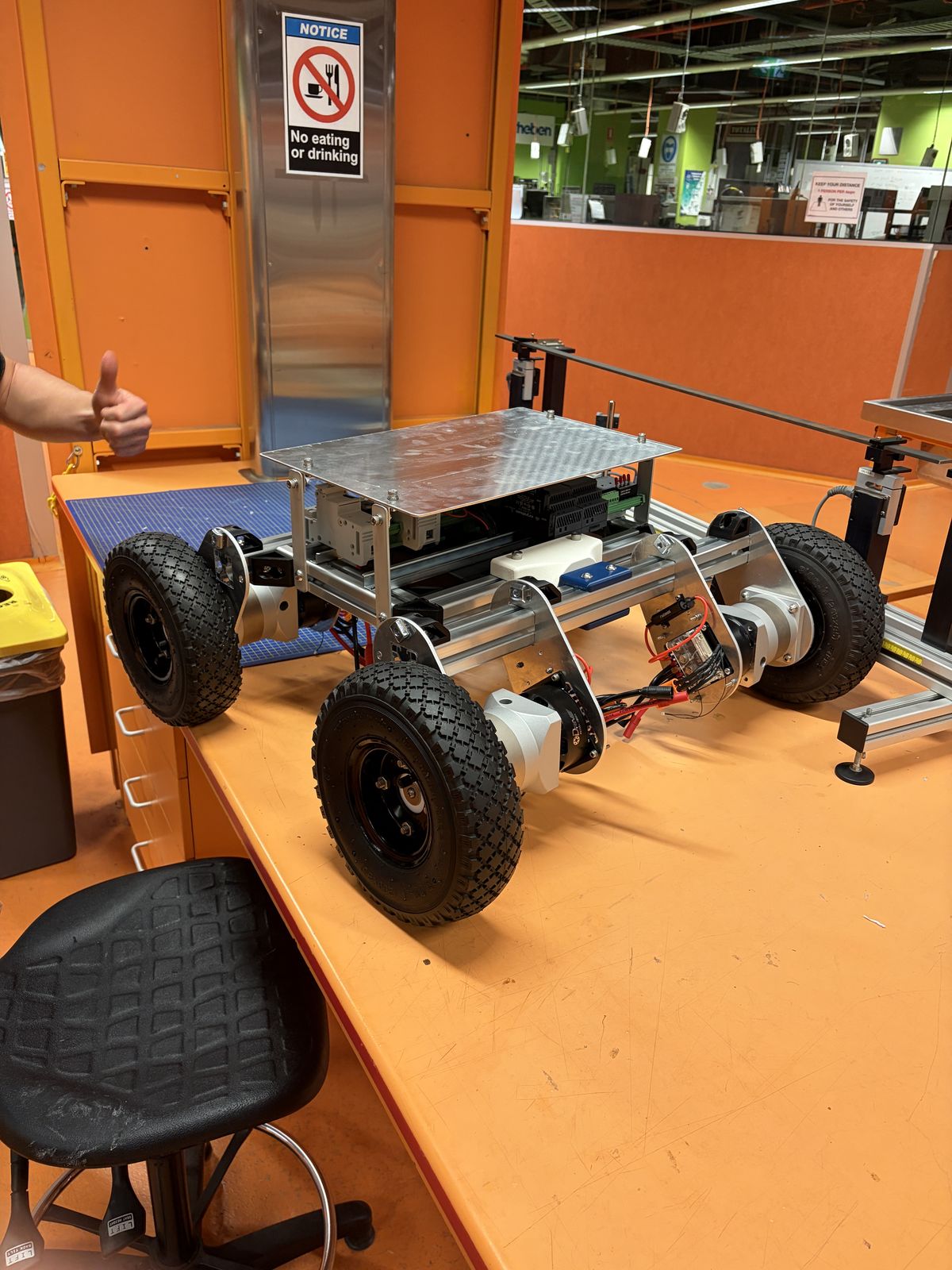
Prototype 2 is 4040 aluminium extrusion on 260 mm pneumatic wheels. Each wheel has its own ODrive M8325s motor through a 10:1 gearbox, sized for a 6 km/h design speed: 122 rpm at the wheel, 1,220 rpm at the motor.

The first motor hubs were 3D printed and split along their layer lines inside the gearbox. Machined aluminium hubs replaced them.

16 September 2026

Power, compute and sensors

Two 16,000 mAh 6S packs in series give 50.4 V through a Batrium battery management system and two contactors. A Raspberry Pi 5 runs the rover software, a Jetson Orin runs obstacle detection on the ZED 2i stereo camera, and a long-range radio links the rover to a base station.

Prototype 2 first drove on 3 September.

16 October 2026

Out of the lab

By mid-October the rover was running on grass. The build record, with the driveline, the power system and the software layers, is on the Rover page.

07 Safety

Six ways to stop

Nobody rides on this machine, so it has to stop itself, and the part that stops it can't be the part that failed. We put each stop in the lowest layer that can still do the job.

Works with every computer off

Physical E-stop Hardware only

Opens contactor 1, which drops logic and motor power together.

BMS fault BMS relay

A cell, temperature or current limit opens the Watchmon relay, and contactor 1 with it.

Radio link loss Radio + relay

No valid frame for 0.5 s. The heartbeat relay opens contactor 2 and the bridge publishes zero velocity.

Needs the ROS 2 software

Low voltage State machine

Pack or bus below 40.8 V, which is 3.4 V a cell. Zero velocity, and contactor 2 opens.

Remote E-stop Radio + ROS 2

The stop key at the base station. Zero velocity, the mission halts, and contactor 2 opens.

Obstacle Jetson + ROS 2

Anything inside 3 m, or a camera that goes silent. The rover holds until the way is clear, then carries on.

100msfor the physical E-stop to pull the main bus below 1 V Rover
0.5mstopping distance at about 1 m/s, inside the 1 m target Rover
2 of 2faults in autonomous mode that the rover's own monitoring caught and latched Field
Not yet shown

A physical stop on radio link loss with the rover moving. The software dry run passed this case. The moving rover hasn't been tested.

08 Field test

Argyle Square, 13 and 14 October

We tested on the paving at Argyle Square in Carlton. Its painted lines and centre disc show up in aerial imagery, which gave us fixed geometry to measure against. RTK corrections came over NTRIP from Geoscience Australia's AUSCORS station EML200AUS0, about 1.4 km away.

First we tested the receiver on its own. Parked over the centre of the disc for ten minutes, a 3D-printed capture box held an RTK fix the whole time, and its position spread 3.8 mm (1σ). Carried twice round a 39 m painted loop, the two laps agreed to 0.057 m RMS.

Then the rover. The operator sent ARM, GO and AUTO from the base-station touchscreen, and Prototype 2 drove itself over the radio link at up to 0.25 m/s. Across three runs it reached all eight points, and it passed within 0.08–0.19 m of every point it reached on RTK.

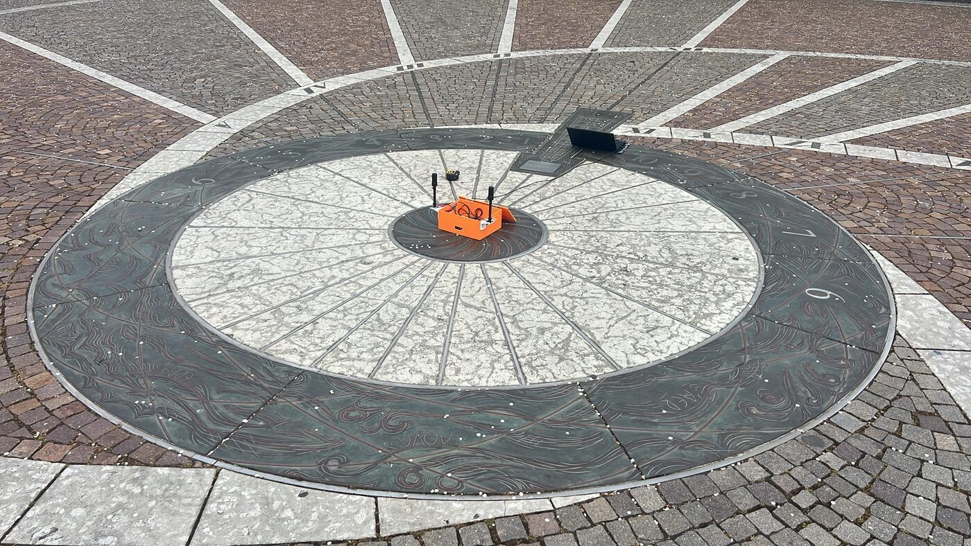
An orange 3D-printed box with two antennas sitting on the dark centre dot of a large painted disc in a paved square.
Reference point R0. The capture box over the centre of the disc.
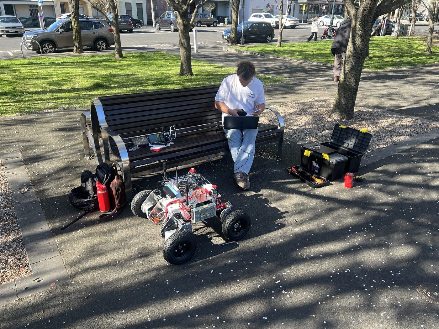
A team member on a park bench with a laptop and the base station, Prototype 2 parked on the path in front, with toolboxes and a fire extinguisher beside the bench.
14 October. Prototype 2, the base station and the laptop streaming corrections.

How close is close enough?

Lateral error in each test against the ±20–50 mm the Knuckey site visit set for neighbouring passes. Log scale.

Show the numbers as a table
TestMeasureValueSource
Receiver parked on R0, 10 minPosition spread, 1σ east (north 3.7 mm)3.8 mmField, 13 Oct
Simulated full paddock, noise-free GNSSNeighbouring-pass spacing error, RMS5.7 mmSimulation
Simulated 17 passes, RTK-grade noiseNeighbouring-pass spacing error, RMS15.8 mmSimulation
Receiver carried round a 39 m loopLap-to-lap offset, RMS57 mmField, 13 Oct
Prototype 2, three long rowsCross-track error, RMSE on RTK samples237–895 mmField, 14 Oct

Between the points, the rover sat 0.24–0.90 m off the line on the long rows, mostly as a steady offset to one side. The receiver resolves millimetres, so the gap points to the control loop: heading or steering bias in the simple route executor that drove these runs, and positions reaching it at 2 Hz, rounded to about 0.1 m.

The controller that tracked to millimetres in simulation hasn't run on Prototype 2 yet. Putting it there is the next job.

Not yet shown

The ±20–50 mm tolerance on the real rover. Each field run was a single attempt on paving at 0.25 m/s, and the GNSS measured itself; nobody surveyed the rover's position independently.

09 Next

What the next team inherits

Future RMIT capstone groups take the Knuckey Rover on from here, with the hardware designs, wiring records, ROS 2 packages, simulation and test procedures. These are the jobs at the top of the list.

  1. Run the simulated controller on Prototype 2Continuous path following with Regulated Pure Pursuit, the heading check before each pass and the staged launch.
  2. Measure against a surveyed tramlineSo tracking error can be read against the ground, not only against the waypoints.
  3. Act on lost RTKTwice the corrections dropped and the rover kept driving on a metre-level fix. Fix type and correction age should slow or stop it.
  4. Lock the CAN connectorsPins pulled out of the ODrive plugs during commissioning. Voltage monitoring and drive commands both run over that bus.
  5. Add a second obstacle sensorLiDAR, for rocks the same colour as the soil.
  6. Plug into the grower's equipmentImport exported John Deere field maps, and take NMEA from the receiver the grower already owns.